
Indoor sensor ESPhome software integration
Introduction
As usual this blog post took longer to finish than anticipated, but it is finally there. I integrated my design for an affordable indoor sensor that can accurate measure CO2 levels, temperature, humidity and air pressure with EPShome. And I must say I was delighted how easy it was to generate the software using ESPhome and a configuration file without having to write a single line of code.
Considerations
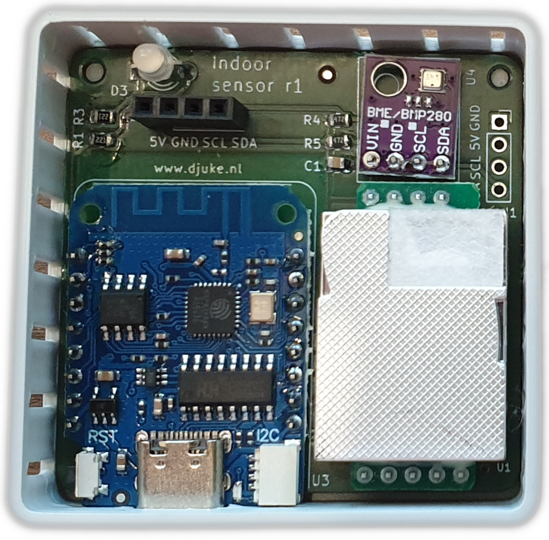
One of the obvious but important requirements of an indoor sensor is that it can accurately measure within the context of the intended use. For a smart indoor sensor that is not trivial (especially for measuring temperature) as there a couple of heat sources that can not be ignored on the PCB:
- ESP8266
- MHZ19 sensor
- SSD1306 OLED display
- Red/green LED
Even though the PCB was designed in such a way that these heat sources are moved as far away as possible to the BME280 sensor, the compact size of the PCB causes these heat sources to affect the BME280 temperature sensor anyway. The effect of the heat sources has to be reduced using a carefully designed housing as the behaviour in a housing differs from open-air operation. But also during the ESPhome software integration this is important by having the option to calibrate the temperature offsets.
Housing
The housing was designed using FreeCAD. It is pretty straightforward and consists of two parts:
- Bottom part where the PCB is attached. It contains ventilation slots at left, top and right side to allow free air flow. The USB-C connection is accesible from the bottom. The rear side has holes for mounting it to a wall.
- Top part that holds the display and can be clicked on the bottom part
Using a 3D printer the housing parts can be printed without the need of supports. It takes about 2 hours in total to print.
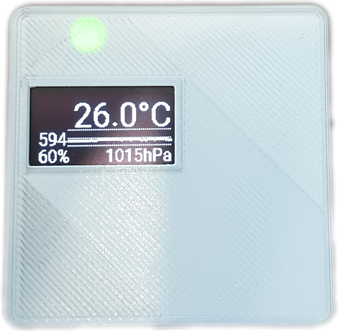
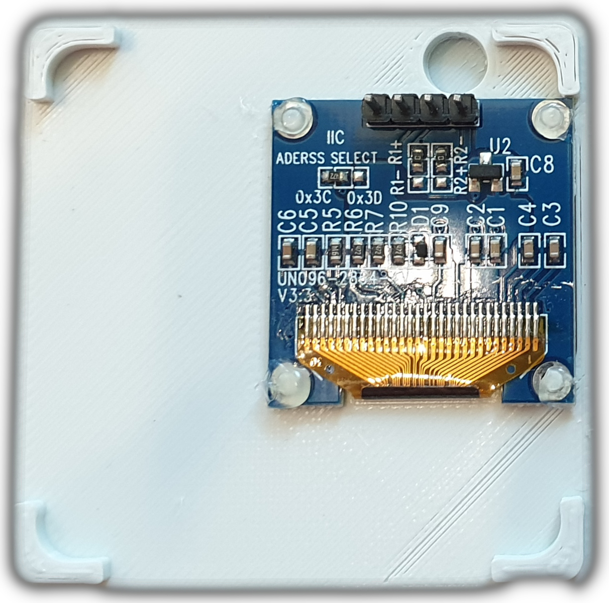
Some pictures of the finished prototype:
ESPhome
I am not afraid of writing a few lines of source code. In this project however, I tried ESPhome and I was impressed. Using only ESPhome and a .yaml configuration file, a working smart indoor sensor can be made that:
- reads all sensors
- controls the LED and display
- connects over WIFI
- makes all measurements easily available in e.g. Home Assistant
Using the indoorsensor.yaml configuration file the firmware can be created and flashed to the target with only this command:
esphome run indoorsensor
The first time, you have to connect it using USB. Once the sensor is connected to your Wifi network, further updates can be done over-the-air.
The full indoorsensor.yaml file can be found in the Indoor sensor Github repo. To give a sneak preview of how it looks like I listed a few sections below.
Substitutions
Substitutions allow keeping the configuration organized and their default values can be adjusted from the command line, e.g.
substitutions:
    devicename: "indoor"
    wifi_ssid: "SSID"
    wifi_password: "Password"
    bme280_temperature_offset: "-8.0"
This way, the Wifi password does not have to be stored in the .yaml file and multiple sensors each with their own device name can be flashed using only one configuration file. Simply run esphome as:
esphome -s devicename indoor-main -s wifi_ssid SSID -s wifi_password PASSWD run indoorsensor
Device/board name
The device and board name have to be added (note how devicename is substituted):
esphome:
  name: ${devicename}

esp8266:
  board: d1_mini
WIFI settings
The WIFI has to be configured and a fallback hotspot will be created in case WIFI connection fails
wifi:
  ssid: ${wifi_ssid}
  password: ${wifi_password}

  # Enable fallback hotspot (captive portal) in case wifi connection fails
  ap:
    ssid: "Indoor sensor Fallback Hotspot"
    password: "Pass1234"

captive_portal:
PIN settings
The LED digital outputs:
output:
  - platform: gpio
    pin: GPIO14
    id: led_red

  - platform: gpio
    pin: GPIO16
    id: led_green
The UART and I2C bus configuration:
uart:
  tx_pin: GPIO0
  rx_pin: GPIO2
  baud_rate: 9600

i2c:
  sda: GPIO4
  scl: GPIO5
  scan: true
Sensor settings
And finally the sensors are all already supported by ESPhome:
sensor:
  - platform: mhz19
    co2:
      name: "CO2 value"
      id: "co2"
    temperature:
      name: "MHZ19 Temperature"
    update_interval: 5s
    automatic_baseline_calibration: false

  - platform: bme280
    temperature:
      name: "BME280 Temperature"
      id: "temp"
    pressure:
      name: "BME280 Pressure"
      id: "pressure"
    humidity:
      name: "BME280 Humidity"
      id: "humidity"
    address: 0x76
    update_interval: 5s
And that is the basic configuration (apart from the display) enough to send the sensor values to Home Assistant.
Functionality
Now some functionality can be added. As an example I want the LED to show:
- green when the CO2 value is below 800ppm
- orange when it is between 800ppm and 1400ppm
- red when the CO2 value is above 1400ppm
This can be easily achieved in the .yaml file by adding the following under the co2: section.
    co2:
      name: "CO2 value"
      id: "co2"
      on_value_range:
        - above: 1400
          then:
            - output.turn_on: led_red
            - output.turn_off: led_green
        - below: 1400
          above: 800
          then:
            - output.turn_on: led_red
            - output.turn_on: led_green
        - below: 800
          then:
            - output.turn_on: led_green
            - output.turn_off: led_red
Other functionality related to sensor offset calibration is found below. Also a 128x64 OLED display was integrated to show the main sensor values.
Offset calibration
The BME280 sensor is relatively accurate. The temperature measurement however is severely affected by the various internal heat sources. To cope with that at least some temperature offset compensation has to be used. In the .yaml file this can be added by applying a filter to the sensor values. For example at the BME280 temperature: section you can add:
      filters:
        - offset: ${bme280_temperature_offset}
Keep the sensor powered on long enough for the inside temperature to have stabilised. Then use a known reference temperature source to adjust the offset until both sensors indicate roughly the same temperature.
Of course this process can be repeated for the other sensors (humidity and air pressure) if you have a good reference available. For air pressure the METAR data of a nearby airport can be used. The air pressure reported by the BME280 I was using was typically within 1hPa of this already.
References
Indoor sensor project
Indoor sensor housing
Indoor sensor sofware
ESPhome